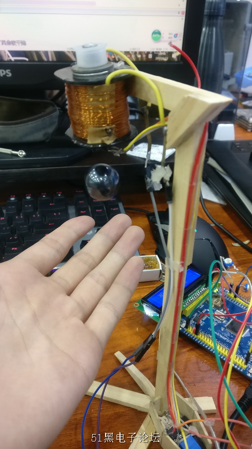
上学期做的课程设计的一部分,
以前做过基于模电的磁悬浮,误差很大,调节不方便,需要多各元件进行,三极管发热的情况也不容乐观。所以在学习stm32的adc功能之后,想使用stm32单片机取代电位比较器。 stm32的adc功能比较强大,根据读的st官方技术手册,使用多通道后,adc的采样速度甚至能达到us级,能满足很多设计要求很高的场景,足够磁悬浮使用。
1. 了解掌握stm32的综合运用方法 2. 加强了解 l298模块的使用 3. 加强了解霍尔传感器的使用 4. 加强了解 adc的使用
二、主要仪器设备、试剂或材料
1. PC,stm32 2. 霍尔传感器 3. L298n 4. 杜邦线 电线若干
001

三、实验方法与步骤 代码(部分)
- /* Includes------------------------------------------------------------------*/
- //# include <stdio. h>
- //# include <stdlib. h>
- #include "stm32f10x.h"
- #include"lcd1602.h"
- //#include "misc.h"
- //#include "misc.c"
- #include<stm32f10x_adc.h>
- //#include<stm32f10x_flash.h>
- /********************************宏定义------------------------------------*/
- #define ADC1_DR_Address ((u32)0x4001244C)
- #define ADC3_DR_Address ((u32)0x40013C4C)
- /********************************变量定义------------------------------------*/
- ADC_InitTypeDefADC_InitStructure;
- DMA_InitTypeDefDMA_InitStructure;
- GPIO_InitTypeDefGPIO_InitStructure; //定义GPIO初始化结构体
- vu16 ADC1ConvertedValue = 0,ADC3ConvertedValue = 0;
- ErrorStatus HSEStartUpStatus;
- int AD_value;
- float CountV;
- float Std = (3.3)/4096;
- int CountV1;
- int CountV2;
- int CountV3;
- int hall;
- unsigned int jj = 0;
- //此表为 LED 的字模, 共阴数码管 0-9 -
- unsigned int Disp_Tab[] ={0x3f,0x06,0x5b,0x4f,0x66,0x6d,0x7d,0x07,0x7f,0x6f,0x40}; //段码控制
- //此表为8个数码管位选控制, 共阴数码管 1-8个 -
- unsigned intdispbit[8]={0xfe,0xfd,0xfb,0xf7,0xef,0xdF,0xbF,0x7F}; //位选控制 查表的方法控制
- unsigned int LedOut[10]; //变量定义
-
- /*********************************声明函数 -----------------------------------------------*/
- void RCC_Configuration(void);
- voidGPIO_Configuration(void);
- voidNVIC_Configuration(void);
- void delay_nms(u16 time);
- void Delay(vu32 nCount);
- /*******************************************************************************
- *
- * 主函数
- *
- *******************************************************************************/
- int main(void)
- { unsigned int LedNumVal = 0 ,LedNumVal1 = 0; //变量定义
- #ifdef DEBUG
- debug();
- #endif
-
- //RCC配置
- RCC_Configuration();
- // NVIC配置
- NVIC_Configuration();
- //GPIO配置
- GPIO_Configuration();
- //DMA1 通道配置
- DMA_DeInit(DMA1_Channel1); //设置成CH1 DMA中包含了7个通道(CH1-CH7)
- DMA_InitStructure.DMA_PeripheralBaseAddr =ADC1_DR_Address; //给DMA起始地址
- DMA_InitStructure.DMA_MemoryBaseAddr =(u32)&ADC1ConvertedValue;//DMA连接在内存中的变量地址
- DMA_InitStructure.DMA_DIR =DMA_DIR_PeripheralSRC; //设置DMA传输方向单向传输
- DMA_InitStructure.DMA_BufferSize = 1; //设置DMA在传输时缓冲区的长度
- DMA_InitStructure.DMA_PeripheralInc =DMA_PeripheralInc_Disable; //设置DMA的外设递增模式
- DMA_InitStructure.DMA_MemoryInc =DMA_MemoryInc_Disable;//设置DMA的内存递增模式
- DMA_InitStructure.DMA_PeripheralDataSize =DMA_PeripheralDataSize_HalfWord;//DMA在访问时每次操作的数据长度
- DMA_InitStructure.DMA_MemoryDataSize =DMA_MemoryDataSize_HalfWord;
- DMA_InitStructure.DMA_Mode =DMA_Mode_Circular;//DMA的传输模式,连续不断的循环模式
- DMA_InitStructure.DMA_Priority =DMA_Priority_High; //DMA的优先级别:可以分为4级
- DMA_InitStructure.DMA_M2M =DMA_M2M_Disable;//DMA的2个memory中的变量互相访问的
- DMA_Init(DMA1_Channel1, &DMA_InitStructure);//DMA整个模块初始化
- //开启DMA通道1
- DMA_Cmd(DMA1_Channel1, ENABLE);
-
- // ADC1 配置
- ADC_InitStructure.ADC_Mode =ADC_Mode_FastInterl; //ADC1工作在独立模式
- ADC_InitStructure.ADC_ScanConvMode =ENABLE;//使能扫描
- ADC_InitStructure.ADC_ContinuousConvMode =ENABLE;;//ADC转换工作在连续模式
- ADC_InitStructure.ADC_ExternalTrigConv =ADC_ExternalTrigConv_None;//由软件控制转换
- ADC_InitStructure.ADC_DataAlign =ADC_DataAlign_Right;//转换数据右对齐
- ADC_InitStructure.ADC_NbrOfChannel = 14;//转换通道为通道1
- ADC_Init(ADC1, &ADC_InitStructure); //初始化ADC
- //ADC1选择信道14,音序器等级1,采样时间239.5个周期
- ADC_RegularChannelConfig(ADC1,ADC_Channel_14, 1, ADC_SampleTime_28Cycles5);
- //使能ADC1模块DMA
- ADC_DMACmd(ADC1, ENABLE);
- //打开ADC1
- ADC_Cmd(ADC1, ENABLE);
- //重置ADC1校准寄存器
- ADC_ResetCalibration(ADC1);
- //等待ADC1校准重置完成
- while(ADC_GetResetCalibrationStatus(ADC1));
- //开始ADC1校准
- ADC_StartCalibration(ADC1);
- //等待ADC1校准完成
- while(ADC_GetCalibrationStatus(ADC1));
- //使能ADC1软件开始转换
- ADC_SoftwareStartConvCmd(ADC1, ENABLE);
- //*****************************************************************************//
- L1602_init();
- L1602_Clear();
- GPIO_SetBits(GPIOC,GPIO_Pin_2);
- L1602_string(1,1," wj works ");
- L1602_string(2,1," ALL SET OK ");
- delay_nms(1000);
- while (1)
- { unsignedint i ;
-
- // L1602_Clear();
- int num = 100;
- int str[4];
- //itoa(num, str, 10);
- AD_value =ADC_GetConversionValue(ADC1);
- CountV = ADC_GetConversionValue(ADC1)* Std;
- CountV1 = CountV/1;
- str[0] = CountV1 ;
-
- // "WJWORKSVoltage "
- //L1602_string(1,1,"WJWORKS");
- //L1602_string(2,1,"Voltage is ");
- //L1602_DispFloatNum(2,12,CountV);
- // L1602_string(2,16,"V");
- if(CountV>=1.1) GPIO_SetBits(GPIOE,GPIO_Pin_5);
- elseGPIO_ResetBits(GPIOE,GPIO_Pin_5);
- //delay_nms(200);
- }
- }
- void Delay(vu32 nCount)
- {
- for(; nCount != 0; nCount--);
- }
- /*******************************************************************************
- *
- * RCC配置
- *
- *******************************************************************************/
- void RCC_Configuration(void)
-
-
- {
- //复位RCC外部设备寄存器到默认值
- RCC_DeInit();
- RCC_APB2PeriphClockCmd(RCC_APB2Periph_GPIOA,ENABLE);//使能GPIOB的时钟
- RCC_APB2PeriphClockCmd(RCC_APB2Periph_GPIOC,ENABLE);//使能GPIOB的时钟
- RCC_APB2PeriphClockCmd(RCC_APB2Periph_GPIOB,ENABLE);//使能GPIOB的时钟
- RCC_APB2PeriphClockCmd(RCC_APB2Periph_GPIOE,ENABLE);//使能GPIOA的时钟
- RCC_APB2PeriphClockCmd(RCC_APB2Periph_GPIOD,ENABLE);//使能GPIOD的时钟
- RCC_APB2PeriphClockCmd(RCC_APB2Periph_USART1,ENABLE);//打开USART的定时器
-
- RCC_APB2PeriphClockCmd(RCC_APB2Periph_AFIO,ENABLE);
- //打开外部高速晶振
- RCC_HSEConfig(RCC_HSE_ON);
- //等待外部高速时钟准备好
- HSEStartUpStatus = RCC_WaitForHSEStartUp();
- //外部高速时钟已经准别好
- if(HSEStartUpStatus == SUCCESS)
- {
-
- FLASH_PrefetchBufferCmd(FLASH_PrefetchBuffer_Enable);
-
- FLASH_SetLatency(FLASH_Latency_2);
-
- //配置AHB(HCLK)时钟=SYSCLK
- RCC_HCLKConfig(RCC_SYSCLK_Div1);
-
- //配置APB2(PCLK2)钟=AHB时钟
- RCC_PCLK2Config(RCC_HCLK_Div1);
- //配置APB1(PCLK1)钟=AHB 1/2时钟
- RCC_PCLK1Config(RCC_HCLK_Div2);
- //配置ADC时钟=PCLK2 1/4
- RCC_ADCCLKConfig(RCC_PCLK2_Div4);
-
- //配置PLL时钟 == 外部高速晶体时钟*9
- RCC_PLLConfig(RCC_PLLSource_HSE_Div1,RCC_PLLMul_9);
-
- //配置ADC时钟= PCLK2/4
- RCC_ADCCLKConfig(RCC_PCLK2_Div4);
- //使能PLL时钟
- RCC_PLLCmd(ENABLE);
- //等待PLL时钟就绪
- while(RCC_GetFlagStatus(RCC_FLAG_PLLRDY) ==RESET)
- {
- }
- //配置系统时钟 = PLL时钟
- RCC_SYSCLKConfig(RCC_SYSCLKSource_PLLCLK);
- //检查PLL时钟是否作为系统时钟
- while(RCC_GetSYSCLKSource() != 0x08)
- {
- }
- }
- // 开启DMA1时钟 Enable
- RCC_AHBPeriphClockCmd(RCC_AHBPeriph_DMA1 ,ENABLE);
- //开启ADC1时钟
- RCC_APB2PeriphClockCmd(RCC_APB2Periph_ADC1 , ENABLE);
-
- //下面是给各模块开启时钟
- //启动GPIO
- RCC_APB2PeriphClockCmd(RCC_APB2Periph_GPIOA| RCC_APB2Periph_GPIOB ,ENABLE);
- //启动AFIO
- RCC_APB2PeriphClockCmd(RCC_APB2Periph_AFIO,ENABLE);
- //启动DMA时钟
- RCC_AHBPeriphClockCmd(RCC_AHBPeriph_DMA1,ENABLE);
- //启动ADC1时钟
- RCC_APB2PeriphClockCmd(RCC_APB2Periph_ADC1,ENABLE);
- }
- /*************************************************
- 函数: voidGPIO_Config(void)
- 功能: GPIO配置
- **************************************************/
- void GPIO_Configuration(void)
- {
-
- RCC_APB2PeriphClockCmd(RCC_APB2Periph_GPIOC,ENABLE);//| RCC_APB2Periph_GPIOB | RCC_APB2Periph_AFIO
- GPIO_PinRemapConfig(GPIO_Remap_SWJ_Disable,ENABLE);
- GPIO_InitStructure.GPIO_Pin = GPIO_Pin_All;
- GPIO_InitStructure.GPIO_Mode =GPIO_Mode_Out_PP;
- GPIO_InitStructure.GPIO_Speed =GPIO_Speed_50MHz; //引脚频率50M
- GPIO_Init(GPIOB, &GPIO_InitStructure);
-
- GPIO_InitStructure.GPIO_Mode=GPIO_Mode_Out_PP;//-------------------------------------输出配置
- GPIO_InitStructure.GPIO_Speed=GPIO_Speed_50MHz;
- GPIO_InitStructure.GPIO_Pin=GPIO_Pin_2;
- GPIO_Init(GPIOC,&GPIO_InitStructure);
-
-
- //配置PA0为模拟输入
- GPIO_InitStructure.GPIO_Pin = GPIO_Pin_15;
- GPIO_InitStructure.GPIO_Mode = GPIO_Mode_Out_PP;
- GPIO_Init(GPIOA, &GPIO_InitStructure);
- GPIO_InitStructure.GPIO_Pin = GPIO_Pin_0;
- GPIO_InitStructure.GPIO_Mode = GPIO_Mode_AIN;
- GPIO_Init(GPIOA, &GPIO_InitStructure);
-
-
- GPIO_InitStructure.GPIO_Mode=GPIO_Mode_Out_PP;//*************指示灯配置
- GPIO_InitStructure.GPIO_Speed=GPIO_Speed_50MHz;
- GPIO_InitStructure.GPIO_Pin=GPIO_Pin_6;
- GPIO_Init(GPIOE,&GPIO_InitStructure);
- GPIO_InitStructure.GPIO_Mode=GPIO_Mode_Out_PP;
- GPIO_InitStructure.GPIO_Speed=GPIO_Speed_50MHz;
- GPIO_InitStructure.GPIO_Pin=GPIO_Pin_5;
- GPIO_Init(GPIOE,&GPIO_InitStructure);
-
- GPIO_InitStructure.GPIO_Mode=GPIO_Mode_Out_PP;//-------------------------------------输出配置
- GPIO_InitStructure.GPIO_Speed=GPIO_Speed_50MHz;
- GPIO_InitStructure.GPIO_Pin=GPIO_Pin_0|GPIO_Pin_5|GPIO_Pin_7|GPIO_Pin_13|GPIO_Pin_14;
- GPIO_Init(GPIOD,&GPIO_InitStructure);
-
- GPIO_InitStructure.GPIO_Mode=GPIO_Mode_Out_PP;//-------------------------------------输出配置
- GPIO_InitStructure.GPIO_Speed=GPIO_Speed_50MHz;
- GPIO_InitStructure.GPIO_Pin=GPIO_Pin_7;
- GPIO_Init(GPIOB,&GPIO_InitStructure);
-
- GPIO_InitStructure.GPIO_Mode=GPIO_Mode_Out_PP;//-------------------------------------输出配置
- GPIO_InitStructure.GPIO_Speed=GPIO_Speed_50MHz;
- GPIO_InitStructure.GPIO_Pin=GPIO_Pin_6;
- GPIO_Init(GPIOA,&GPIO_InitStructure);
-
- GPIO_InitStructure.GPIO_Mode=GPIO_Mode_Out_PP;//-------------------------------------输出配置
- GPIO_InitStructure.GPIO_Speed=GPIO_Speed_50MHz;
- GPIO_InitStructure.GPIO_Pin=GPIO_Pin_7|GPIO_Pin_9|GPIO_Pin_11|GPIO_Pin_13;
- GPIO_Init(GPIOE,&GPIO_InitStructure);
-
- GPIO_InitStructure.GPIO_Mode=GPIO_Mode_Out_PP;//-------------------------------------输出配置
- GPIO_InitStructure.GPIO_Speed=GPIO_Speed_50MHz;
- GPIO_InitStructure.GPIO_Pin=GPIO_Pin_2;
- GPIO_Init(GPIOC,&GPIO_InitStructure);
-
- GPIO_InitStructure.GPIO_Mode=GPIO_Mode_Out_PP;//-------------------------------------输出配置d10
- GPIO_InitStructure.GPIO_Speed=GPIO_Speed_50MHz;
- GPIO_InitStructure.GPIO_Pin=GPIO_Pin_10;
- GPIO_Init(GPIOD,&GPIO_InitStructure);
- }
- void delay_nms(u16 time)
- {
- u16 i=0;
- while(time--)
- {
- i=12000;
- while(i--) ;}}
-
- /*******************************************************************************
- * Function Name : NVIC_Configuration
- * Description : Configures Vector Table base location.
- * Input : None
- * Output : None
- * Return : None
- *******************************************************************************/
- void NVIC_Configuration(void)
- {
- NVIC_InitTypeDef NVIC_InitStructure;
- #ifdef VECT_TAB_RAM
- /* Set the Vector Table base location at0x20000000 */
- NVIC_SetVectorTable(NVIC_VectTab_RAM, 0x0);
- #else /* VECT_TAB_FLASH */
- /* Set the Vector Table base location at0x08000000 */
- NVIC_SetVectorTable(NVIC_VectTab_FLASH,0x0);
- #endif
- /* Configure and enable ADC interrupt */
- NVIC_InitStructure.NVIC_IRQChannel =ADC1_2_IRQn;
- NVIC_InitStructure.NVIC_IRQChannelPreemptionPriority = 0;
- NVIC_InitStructure.NVIC_IRQChannelSubPriority= 0;
- NVIC_InitStructure.NVIC_IRQChannelCmd =ENABLE;
- NVIC_Init(&NVIC_InitStructure);
- }
- #ifdef DEBUG
- /*******************************************************************************
- * Function Name : assert_failed
- * Description : Reports the name of the source file andthe source line number
- * where the assert_param errorhas occurred.
- * Input : - file: pointer to the source filename
- * - line: assert_param errorline source number
- * Output : None
- * Return : None
- *******************************************************************************/
- void assert_failed(u8* file,u32 line)
- {
- /* User can add his own implementation toreport the file name and line number,
- ex: printf("Wrong parameters value:file %s on line %d\r\n", file, line) */
- /* Infinite loop */
- while (1)
- {
- }
- }
- #endif
四、实验总结 弥补了之前使用电位比较器的缺点,因为点位比较器没有反馈的机制,所以最后小球在空中震荡的频率会越来越快,最后超过阈值会吸在通电线圈上。 现在通过stm32可以通过程序,例如 增加一个刹车的机制,设置一个随时间变化的比例,通过改变in1,in2,ena的电平状态,逐步增加刹车时间,完成稳定悬浮体的作用。
|