编码器分类: 按工作原理:光电式、磁电式和触点电刷式 按码盘的刻孔方式:增量式和绝对式两类 由于博主接触面还不是很广,一共就用过两个种类的编码器,都是属于光电的 差分编码器:一般由8根线连接 信号线分别为 A+ A- B+ B- Z+ Z- 以及VCC和GND 这里有一种不需要Z信号的,6线差分A+ A- B+ B- VCC 和GND 正交编码器:一般是5根线连接,信号线分别为A B Z VCC和GND
编码器线数: 就是旋转一圈你的A(B)会输出多少个脉冲 ,这里的A B就是上面的输出脉冲信号线,它们转一圈发出的脉冲数一样的,不过存在90°相位差 通常都是360线的 线数越高代表编码器能够反应的位置精度越高
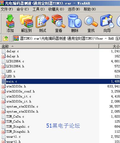
单片机源程序如下:
- //光电编码器测速,TIM3_ETR,PD2
- #include "stm32f10x.h"
- #include <stdio.h>
- #include "TIM_CeSu.h"
- #include "TIM_Dingshi.h"
- #include "LED.h"
- #include "LCD12864.h"
- #include "delay.h"
- uint16_t Qian_Count,Hou_Count;
- uint8_t flag;
- float speed;
- void Board_Init(void)
- {
- LED_Init();
- NVIC_Config();
- Timer_Init();
- TIM_Init();
- InitDis();
- }
- int main(void)
- {
- Board_Init();
- locate16(1,1);
- DisStr(" 编码器测速");
- delay_ms(10);
- while(1)
- #if 1
- {
- locate16(2,1);
- DisStr("当前编码器速度:");
- delay_ms(10);
- locate16(3,1);
- lcd_decimal(speed);
- delay_ms(10);
- DisStr(" 圈/ 秒");
- }
- #endif
- }
- void TIM3_IRQHandler(void)
- {
- #if 0
- if(TIM_GetITStatus(TIM1,TIM_IT_Update) != RESET)
- {
- //TIM_ClearITPendingBit(TIM1,TIM_IT_Update); //清除标志位
- GPIOC-> ODR ^= GPIO_Pin_6;
- TIM_ClearITPendingBit(TIM1, TIM_FLAG_Update); //清中断
- //TIM1->EGR |= 0x0001;
- //TIM_ClearITPendingBit(TIM1, TIM_FLAG_Update); //清中断
- }
- #endif
- if(TIM_GetITStatus(TIM3,TIM_IT_Update) != RESET)
- {
- TIM_ClearITPendingBit(TIM3,TIM_IT_Update); //清除标志位
- GPIOC-> ODR ^= GPIO_Pin_8;
- flag++;
- }
- }
- //定时器2的中断函数
- void TIM2_IRQHandler(void)
- {
- if(TIM_GetITStatus(TIM2,TIM_IT_Update) != RESET)
- {
- TIM_ClearITPendingBit(TIM2,TIM_IT_Update); //清除标志位
- GPIOC-> ODR ^= GPIO_Pin_9;
- Qian_Count = TIM3->CNT;
- speed=(800*flag+Qian_Count-Hou_Count)*2.0/200.0;
- ……………………
- …………限于本文篇幅 余下代码请从51黑下载附件…………

所有资料51hei提供下载:
 光电编码器测速(通用定时器TIM3).rar
(274.5 KB, 下载次数: 521)
|