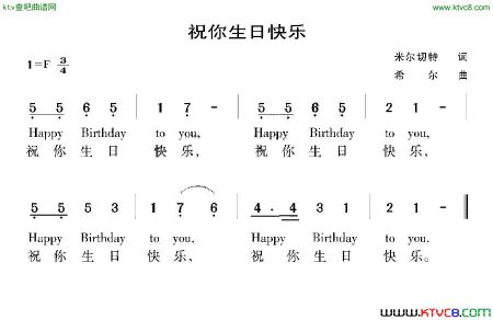
stm32电子工艺实习作品


单片机源程序如下:
- /******************** (C) COPYRIGHT 2007 STMicroelectronics ********************
- * File Name : main.c
- * Author : MCD Application Team
- * Version : V1.0
- * Date : 10/08/2007
- * Description : Main program body
- ********************************************************************************
- * THE PRESENT SOFTWARE WHICH IS FOR GUIDANCE ONLY AIMS AT PROVIDING CUSTOMERS
- * WITH CODING INFORMATION REGARDING THEIR PRODUCTS IN ORDER FOR THEM TO SAVE TIME.
- * AS A RESULT, STMICROELECTRONICS SHALL NOT BE HELD LIABLE FOR ANY DIRECT,
- * INDIRECT OR CONSEQUENTIAL DAMAGES WITH RESPECT TO ANY CLAIMS ARISING FROM THE
- * CONTENT OF SUCH SOFTWARE AND/OR THE USE MADE BY CUSTOMERS OF THE CODING
- * INFORMATION CONTAINED HEREIN IN CONNECTION WITH THEIR PRODUCTS.
- *******************************************************************************/
- /* Includes ------------------------------------------------------------------*/
- #include "stm32f10x_lib.h"
- #include "math.h"
- #include "stdio.h"
- int fputc(int ch,FILE *f);
- /* Private typedef -----------------------------------------------------------*/
- /* Private define ------------------------------------------------------------*/
- #define ADC1_DR_Address ((u32)0x4001244C)
- //ADC1 4001 2400H
- //ADC_DR偏移地址 4CH
- volatile u16 ADC_Ch0_Res, ADC_Ch1_Res, ADC_Ch2_Res, ADC_Ch3_Res;
- volatile u16 ADC_RegularConvertedValueTab[1];
- u32 ADC_Calibration_DR;
- u32 shownum=0;
- /* Private macro -------------------------------------------------------------*/
- /* Private variables ---------------------------------------------------------*/
- ADC_InitTypeDef ADC_InitStructure;
- DMA_InitTypeDef DMA_InitStructure;
- USART_InitTypeDef USART_InitStructure;
- USART_ClockInitTypeDef USART_ClockInitStructure;
- TIM_TimeBaseInitTypeDef TIM_TimeBaseStructure;
- TIM_OCInitTypeDef TIM_OCInitStructure;
- ErrorStatus HSEStartUpStatus;
- /* Private function prototypes -----------------------------------------------*/
- void USART_Configuration(void);
- void DMA_Configuration(void);
- void ADC_Configuration(void);
- void RCC_Configuration(void);
- void GPIO_Configuration(void);
- void NVIC_Configuration(void);
- void TIM1_Configuration(void);
- void TIM2_Configuration(void);
- void Delay(vu32 nCount);
- /* Private functions ---------------------------------------------------------*/
- /*******************************************************************************
- * Function Name : main
- * Description : Main program
- * Input : None
- * Output : None
- * Return : None
- *******************************************************************************/
- int main(void)
- {
- // u16 i=0;
- // u32 sum=0;
- #ifdef DEBUG
- debug();
- #endif
- /* System Clocks Configuration */
- RCC_Configuration();
- /* NVIC configuration */
- NVIC_Configuration();
- /* Configure the GPIO ports */
- GPIO_Configuration();
- /* USART1 configuration ------------------------------------------------------*/
- USART_Configuration();
- /* DMA Channel1 Configuration ----------------------------------------------*/
- DMA_Configuration();
-
-
- /* ADC1 configuration ------------------------------------------------------*/
- ADC_Configuration();
- TIM1_Configuration();
- TIM2_Configuration();
-
- while(1)
- {
-
- }
-
- }
- void TIM1_Configuration(void)
- {
- /* ---------------------------------------------------------------
- TIM2 Configuration: Output Compare Inactive Mode:
- TIM2CLK = 36 MHz, Prescaler = 35999, TIM2 counter clock = 1 KHz
- --------------------------------------------------------------- */
- /* Time base configuration */
- TIM_TimeBaseStructure.TIM_Period = 300-1; //定时周期
- // T = (TIM_Period+1)*(TIM_Prescaler+1)/TIMxCLK
- // = (499+1)*(35999+1)/36MHz = 0.5s
- TIM_TimeBaseStructure.TIM_Prescaler = 36000-1; //预分频因子
- TIM_TimeBaseStructure.TIM_ClockDivision = 0; //定时器分频因子
- TIM_TimeBaseStructure.TIM_CounterMode = TIM_CounterMode_Up; //定时器计数模式
- TIM_TimeBaseInit(TIM1, &TIM_TimeBaseStructure);
-
- TIM_ARRPreloadConfig(TIM1, ENABLE);//自动装载寄存器使能
- /* TIM IT enable */
- TIM_ITConfig(TIM1, TIM_IT_Update, ENABLE);
- /* TIM2 enable counter */
- TIM_Cmd(TIM1, ENABLE); //计数器控制寄存器TIMx->CR1中的计数器使能位(CEN)
- }
- void TIM2_Configuration(void)
- {
- /* ---------------------------------------------------------------
- TIM2 Configuration: Output Compare Inactive Mode:
- TIM2CLK = 36 MHz, Prescaler = 35999, TIM2 counter clock = 1 KHz
- --------------------------------------------------------------- */
- /* Time base configuration */
- TIM_TimeBaseStructure.TIM_Period = 2; //定时周期
- // T = (TIM_Period+1)*(TIM_Prescaler+1)/TIMxCLK
- // = (499+1)*(35999+1)/36MHz = 0.5s
- TIM_TimeBaseStructure.TIM_Prescaler = 36000-1; //预分频因子
- TIM_TimeBaseStructure.TIM_ClockDivision = 0; //定时器分频因子
- TIM_TimeBaseStructure.TIM_CounterMode = TIM_CounterMode_Up; //定时器计数模式
- TIM_TimeBaseInit(TIM2, &TIM_TimeBaseStructure);
-
- TIM_ARRPreloadConfig(TIM2, ENABLE);//自动装载寄存器使能
- /* TIM IT enable */
- TIM_ITConfig(TIM2, TIM_IT_Update, ENABLE);
- /* TIM2 enable counter */
- TIM_Cmd(TIM2, ENABLE); //计数器控制寄存器TIMx->CR1中的计数器使能位(CEN)
- }
- void USART_Configuration(void)
- {
- /* USART1 configured as follow:
- - BaudRate = 38400 baud
- - Word Length = 8 Bits
- - One Stop Bit
- - No parity
- - Hardware flow control disabled (RTS and CTS signals)
- - Receive and transmit enabled
- - USART Clock disabled
- - USART CPOL: Clock is active low
- - USART CPHA: Data is captured on the second edge
- - USART LastBit: The clock pulse of the last data bit is not output to
- the SCLK pin
- */
- USART_InitStructure.USART_BaudRate = 38400;//设置波特率为38400
- USART_InitStructure.USART_WordLength = USART_WordLength_8b;// 8位传输
- USART_InitStructure.USART_StopBits = USART_StopBits_1; //1个停止位
- USART_InitStructure.USART_Parity = USART_Parity_No; //无校验位
- USART_InitStructure.USART_HardwareFlowControl=USART_HardwareFlowControl_None;
- USART_InitStructure.USART_Mode = USART_Mode_Rx | USART_Mode_Tx;
- USART_Init(USART1, &USART_InitStructure);
- // 禁止硬件流控制,禁止RTS和CTS信号
- // 允许接收、发送
- /*
- USART_InitStructure.USART_Clock = USART_Clock_Disable;//串口时钟禁止
- USART_InitStructure.USART_CPOL = USART_CPOL_Low;
- USART_InitStructure.USART_CPHA = USART_CPHA_1Edge;
- USART_InitStructure.USART_LastBit = USART_LastBit_Disable; */
-
- /* Configure the USART1 配置串口的波特率,校验位,停止位和时钟等*/
-
- USART_ClockInitStructure.USART_Clock = USART_Clock_Disable;
- USART_ClockInitStructure.USART_CPOL = USART_CPOL_Low;
- USART_ClockInitStructure.USART_CPHA = USART_CPHA_1Edge;
- USART_ClockInitStructure.USART_LastBit = USART_LastBit_Disable;
- USART_ClockInit(USART1 , &USART_ClockInitStructure);
- /* Enable USART1 使能串口1*/
- USART_Cmd(USART1, ENABLE);
-
- }
- void DMA_Configuration(void)
- {
- DMA_DeInit(DMA1_Channel1);//复位开启DMA1的第一通道
- //DMA对应的外设基地址
- DMA_InitStructure.DMA_PeripheralBaseAddr = ADC1_DR_Address;
-
- //序列1转换结果放在ADC_RegularConvertedValueTab[0],序列2……
- DMA_InitStructure.DMA_MemoryBaseAddr = (u32)ADC_RegularConvertedValueTab;
- //DMA的转换模式:SRC模式,从外设向内存中传送数据
- DMA_InitStructure.DMA_DIR = DMA_DIR_PeripheralSRC;
- DMA_InitStructure.DMA_BufferSize = 1;
- //BufferSize = 4,ADC转换序列有4个通道
-
- //接收一次数据后,设备地址是否后移
- DMA_InitStructure.DMA_PeripheralInc = DMA_PeripheralInc_Disable;
- //接收一次数据后,目标内存地址自动后移,用来采集多个数据
- DMA_InitStructure.DMA_MemoryInc = DMA_MemoryInc_Enable;
-
- //转换结果的数据大小
- DMA_InitStructure.DMA_PeripheralDataSize = DMA_PeripheralDataSize_HalfWord;
- DMA_InitStructure.DMA_MemoryDataSize = DMA_MemoryDataSize_HalfWord;
-
- //转换模式:常用循环缓存模式。Buffer写满后,自动回到初始地址开始传输
- //另外一种Normal模式:不循环,仅一次DMA
- DMA_InitStructure.DMA_Mode = DMA_Mode_Circular;
- DMA_InitStructure.DMA_Priority = DMA_Priority_High;//DMA优先级,高
- DMA_InitStructure.DMA_M2M = DMA_M2M_Disable;//内存到内存模式禁止
- DMA_Init(DMA1_Channel1, &DMA_InitStructure);
- /* Enable DMA channel1 */
- DMA_Cmd(DMA1_Channel1, ENABLE);
- }
- void ADC_Configuration(void)
- {
- /* ADC1 configuration ------------------------------------------------------*/
- ADC_InitStructure.ADC_Mode = ADC_Mode_Independent;//每个ADC独立工作
- //ADC扫描所有规则转换通道ADC_SQRx和注入转换通道ADC_JSQR
- ADC_InitStructure.ADC_ScanConvMode = ENABLE;
- ADC_InitStructure.ADC_ContinuousConvMode = ENABLE;//连续转换模式开启
-
- /*关闭ADC外部触发,即禁止由外部触发模数转换*/
- ADC_InitStructure.ADC_ExternalTrigConv = ADC_ExternalTrigConv_None;
- ADC_InitStructure.ADC_DataAlign = ADC_DataAlign_Right;//转换数据右对齐
- ADC_InitStructure.ADC_NbrOfChannel = 1; //开启4个通道
- ADC_Init(ADC1, &ADC_InitStructure); //调用固件库函数完成初始化
- /* ADC1 regular channel configuration */ //采样周期为239.5个周期
- ADC_RegularChannelConfig(ADC1, ADC_Channel_2, 1, ADC_SampleTime_239Cycles5);
- //转换周期不能太短,否则CPU基本一直处于ADC中断状态
- /* Enable ADC1 DMA */
- ADC_DMACmd(ADC1, ENABLE);/* 使能ADC1 DMA*/
- /* Enable ADC1 ECO*/ //ADC转换完成中断使能
- // ADC_ITConfig(ADC1, ADC_IT_EOC, ENABLE);
-
- /* Enable ADC1 */
- ADC_Cmd(ADC1, ENABLE);
- /* Enable ADC1 reset calibaration register */
- ADC_ResetCalibration(ADC1);// ADC1 复位校准
-
- /* Check the end of ADC1 reset calibration register */
- while(ADC_GetResetCalibrationStatus(ADC1)); //等待校准寄存器初始化
- /* Start ADC1 calibaration */
- ADC_StartCalibration(ADC1);//开始校准
-
- /* Check the end of ADC1 calibration */
- while(ADC_GetCalibrationStatus(ADC1));//等到校准完成
- ADC_Calibration_DR = ADC1->DR;//保存校准码
- /* Start ADC1 Software Conversion */
- ADC_SoftwareStartConvCmd(ADC1, ENABLE);//软件启动ADC1进行连续转换
- //ADC_ITConfig(ADC1, ADC_IT_EOC, ENABLE);
- }
- /*******************************************************************************
- * Function Name : RCC_Configuration
- * Description : Configures the different system clocks.
- * Input : None
- * Output : None
- * Return : None
- *******************************************************************************/
- void RCC_Configuration(void)
- {
- /* RCC system reset(for debug purpose) */
- RCC_DeInit();
- /* Enable HSE */
- // RCC_HSICmd(ENABLE);
- RCC_HSEConfig(RCC_HSE_ON);
- // RCC_LSEConfig(RCC_LSE_OFF);
- while(RCC_GetFlagStatus(RCC_FLAG_HSIRDY) == RESET);
- /* Wait till HSE is ready */
- HSEStartUpStatus = RCC_WaitForHSEStartUp();
- if(HSEStartUpStatus == SUCCESS)
- {
- /* Enable Prefetch Buffer */
- FLASH_PrefetchBufferCmd(FLASH_PrefetchBuffer_Enable);
- /* Flash 2 wait state */
- FLASH_SetLatency(FLASH_Latency_2);
- /* HCLK = SYSCLK */
- RCC_HCLKConfig(RCC_SYSCLK_Div1);
- /* PCLK2 = HCLK */
- RCC_PCLK2Config(RCC_HCLK_Div1);
- /* PCLK1 = HCLK/2 */
- RCC_PCLK1Config(RCC_HCLK_Div2);
- /* PLLCLK = 8MHz * 9 = 72 MHz */
- RCC_PLLConfig(RCC_PLLSource_HSI_Div2, RCC_PLLMul_9);
- /* Enable PLL */
- RCC_PLLCmd(ENABLE);
- /* Wait till PLL is ready */
- while(RCC_GetFlagStatus(RCC_FLAG_PLLRDY) == RESET)
- {
- }
- /* Select PLL as system clock source */
- RCC_SYSCLKConfig(RCC_SYSCLKSource_PLLCLK);
- /* Wait till PLL is used as system clock source */
- while(RCC_GetSYSCLKSource() != 0x08)
- {
- }
- }
- /* Enable DMA clock */
- RCC_AHBPeriphClockCmd(RCC_AHBPeriph_DMA1, ENABLE);
-
- /* Enable GPIOA GPIOB USART1 GPIOC and ADC1 clocks */
- RCC_APB2PeriphClockCmd(RCC_APB2Periph_GPIOA | RCC_APB2Periph_USART1
- | RCC_APB2Periph_GPIOC | RCC_APB2Periph_ADC1
- | RCC_APB2Periph_GPIOB| RCC_APB2Periph_GPIOD
- | RCC_APB2Periph_TIM1, ENABLE);
- RCC_APB1PeriphClockCmd(RCC_APB1Periph_TIM2, ENABLE);
-
- RCC_ADCCLKConfig(RCC_PCLK2_Div6);
- }
- /*******************************************************************************
- * Function Name : GPIO_Configuration
- * Description : Configures the different GPIO ports.
- * Input : None
- * Output : None
- * Return : None
- *******************************************************************************/
- void GPIO_Configuration(void)
- {
- GPIO_InitTypeDef GPIO_InitStructure;
- /* Configure USART1 Tx (PA.09) as alternate function push-pull */
- GPIO_InitStructure.GPIO_Pin = GPIO_Pin_9;
- GPIO_InitStructure.GPIO_Speed = GPIO_Speed_50MHz;
- GPIO_InitStructure.GPIO_Mode = GPIO_Mode_AF_PP;
- GPIO_Init(GPIOA, &GPIO_InitStructure);
- /* Configure USART1 Rx (PA.10) as input floating */
- GPIO_InitStructure.GPIO_Pin = GPIO_Pin_10;
- GPIO_InitStructure.GPIO_Mode = GPIO_Mode_IN_FLOATING;
- GPIO_Init(GPIOA, &GPIO_InitStructure);
- /* Configure PA4 PA5 PA6 and PA7
- (ADC Channel4 Channel5 Channel6 and Channel7) as analog input */
- GPIO_InitStructure.GPIO_Pin = GPIO_Pin_2;
- GPIO_InitStructure.GPIO_Mode = GPIO_Mode_AIN;
- GPIO_Init(GPIOA, &GPIO_InitStructure);
-
-
-
- /* GPIOA Configuration: Pin8 in Output */
- GPIO_InitStructure.GPIO_Pin = GPIO_Pin_10;
- GPIO_InitStructure.GPIO_Speed = GPIO_Speed_50MHz;
- GPIO_InitStructure.GPIO_Mode = GPIO_Mode_Out_PP;
- GPIO_Init(GPIOB, &GPIO_InitStructure);
-
- GPIO_InitStructure.GPIO_Pin = GPIO_Pin_5;
- GPIO_InitStructure.GPIO_Speed = GPIO_Speed_50MHz;
- GPIO_InitStructure.GPIO_Mode = GPIO_Mode_Out_PP;
- GPIO_Init(GPIOC, &GPIO_InitStructure);
-
- }
- /*******************************************************************************
- * Function Name : NVIC_Configuration
- * Description : Configures the nested vectored interrupt controller.
- * Input : None
- * Output : None
- * Return : None
- *******************************************************************************/
- void NVIC_Configuration(void)
- {
- NVIC_InitTypeDef NVIC_InitStructure;
- #ifdef VECT_TAB_RAM
- /* Set the Vector Table base location at 0x20000000 */
- NVIC_SetVectorTable(NVIC_VectTab_RAM, 0x0);
- #else /* VECT_TAB_FLASH */
- /* Set the Vector Table base location at 0x08000000 */
- NVIC_SetVectorTable(NVIC_VectTab_FLASH, 0x0);
- #endif
- // Enable ADC IRQChannel
- NVIC_InitStructure.NVIC_IRQChannel = TIM1_UP_IRQChannel;
- NVIC_InitStructure.NVIC_IRQChannelPreemptionPriority = 0;
- NVIC_InitStructure.NVIC_IRQChannelSubPriority = 0;
- NVIC_InitStructure.NVIC_IRQChannelCmd = ENABLE;
- NVIC_Init(&NVIC_InitStructure);
- NVIC_InitStructure.NVIC_IRQChannel = TIM2_IRQChannel;
- NVIC_InitStructure.NVIC_IRQChannelPreemptionPriority = 0;
- ……………………
- …………限于本文篇幅 余下代码请从51黑下载附件…………
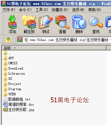
所有资料51hei提供下载:
 生日快乐播放.rar
(494.66 KB, 下载次数: 104)
|